darrenbrown

ProjectsPersonal

Downspout percolation drains

Sized and installed percolation drainage on all four gutter downspouts to stop basement water intrusion
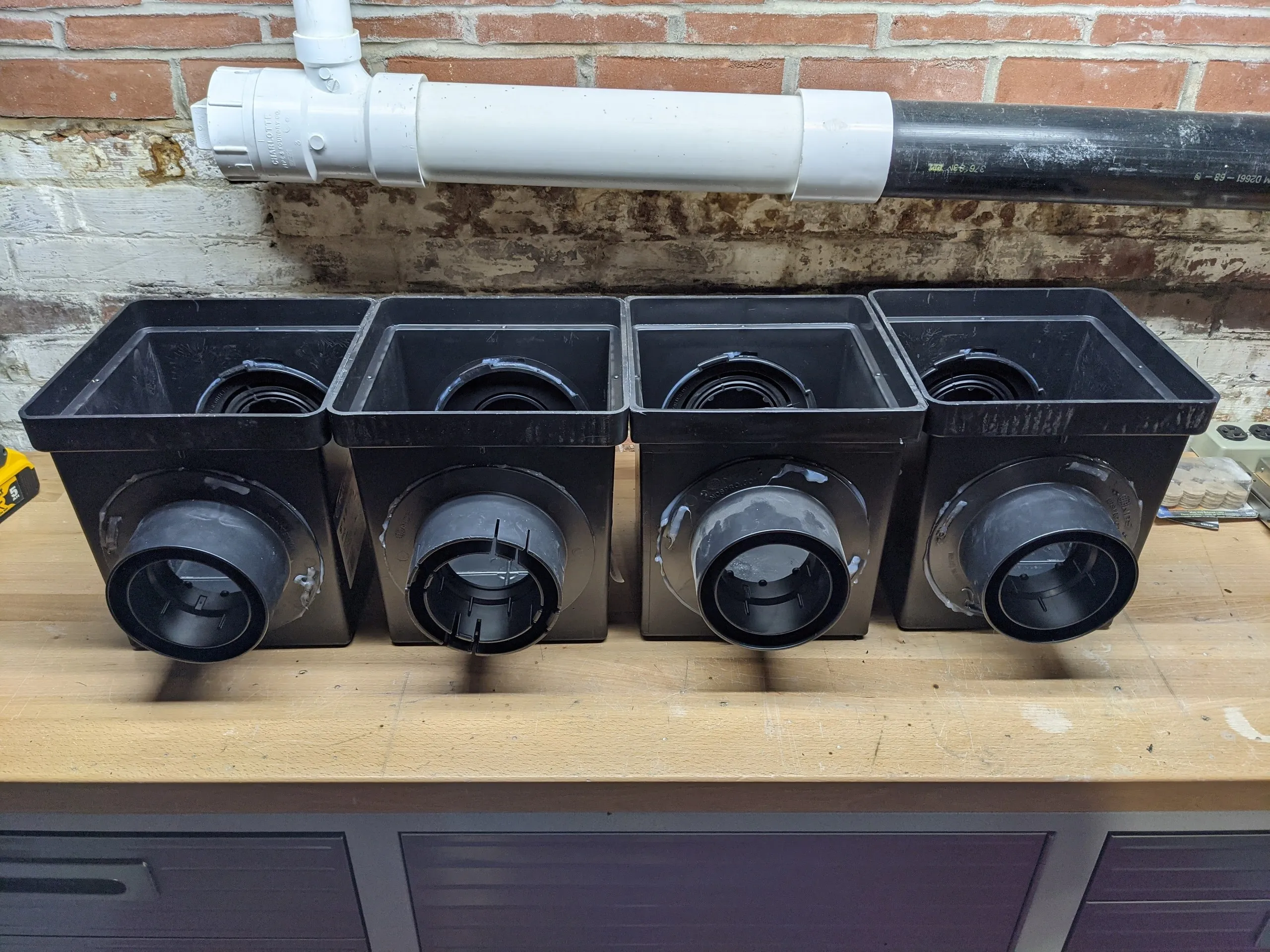
Four catch basins on a workbench, each with a corrugated pipe outlet solvent-welded and sealed with silicone
Catch basins prepped
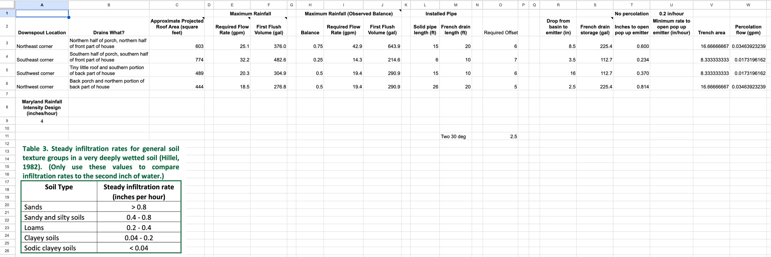
Calculation spreadsheet showing projected roof area, required flow rate, first flush volume, installed pipe length, and percolation flow for each of the four downspout locations, next to a table of steady infiltration rates by soil type
Sizing calculations
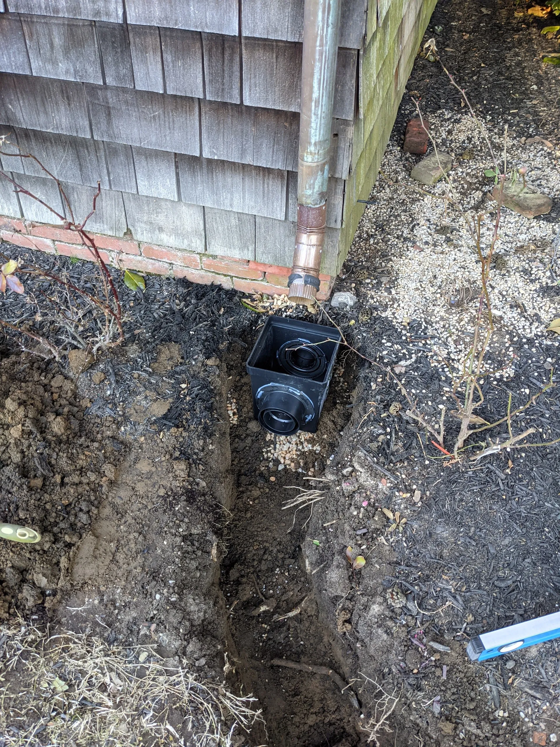
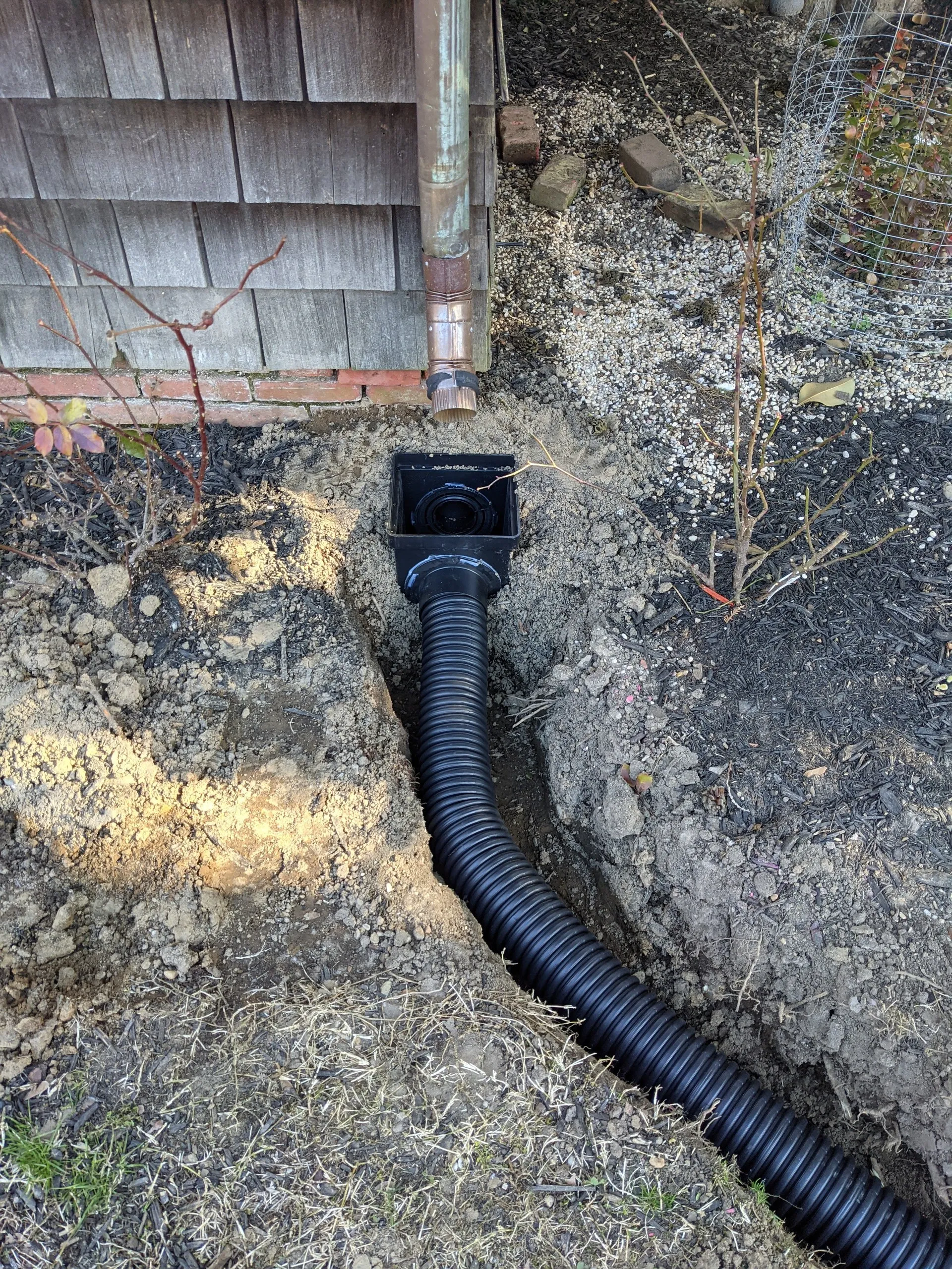
Catch basin set in the ground under a copper downspout, at the corner of the house, with the connecting trench dug alongside it
Basin set under a downspout
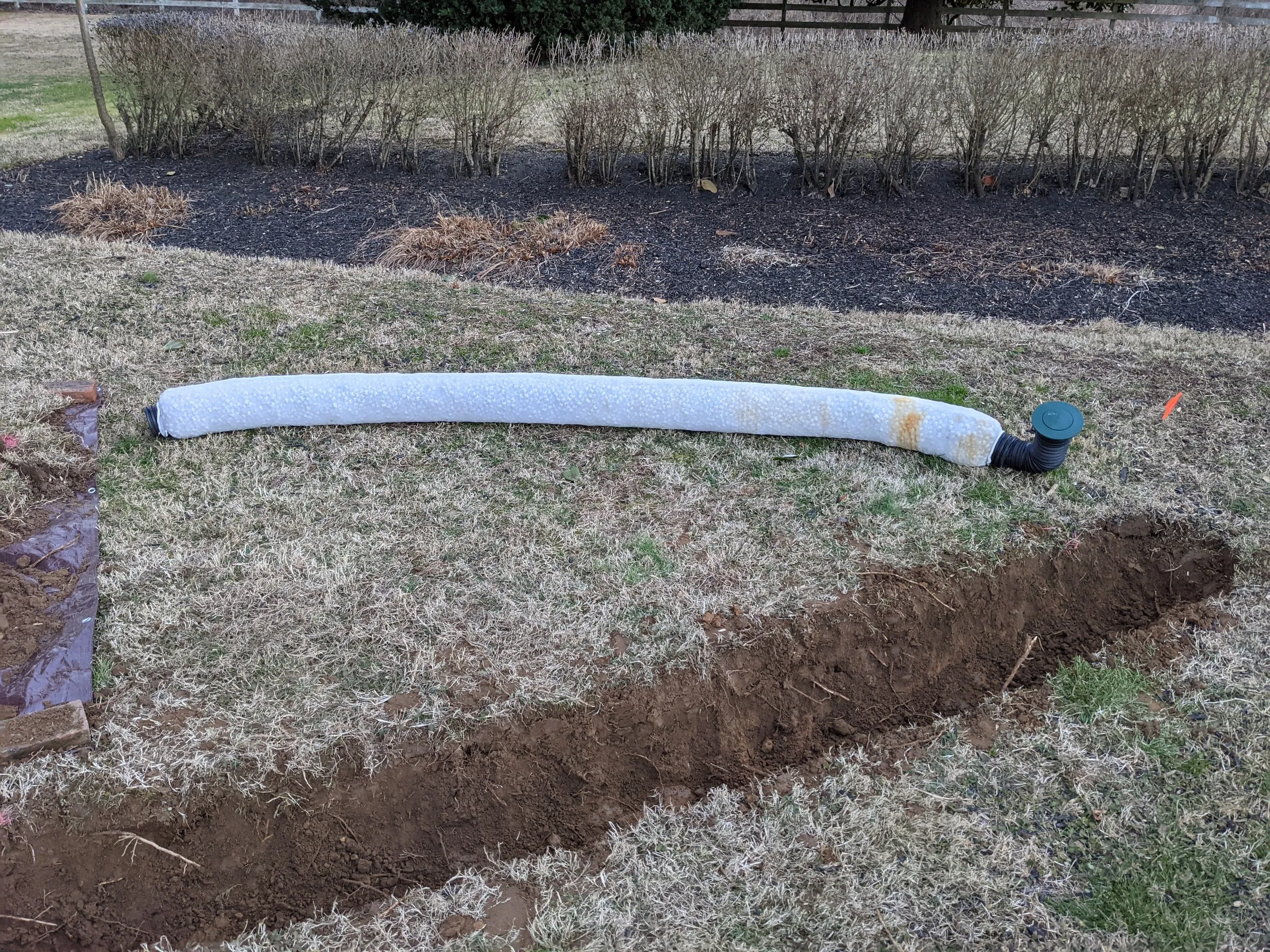
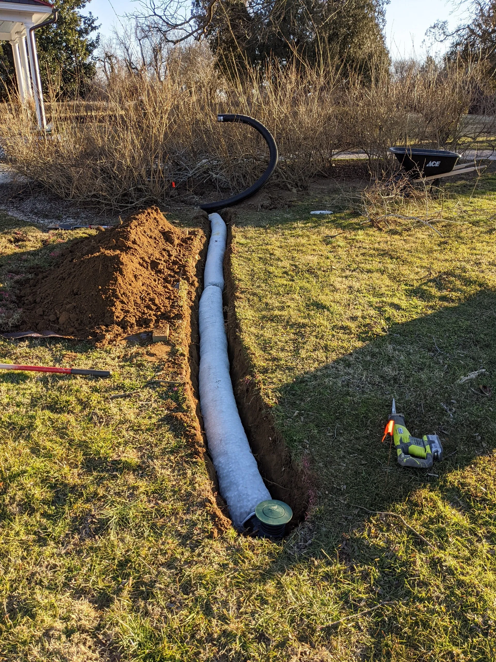
Corrugated pipe wrapped in a fabric sock lying in the grass, running from the trench to a green pop-up emitter
Sock-wrapped pipe to a pop-up emitter
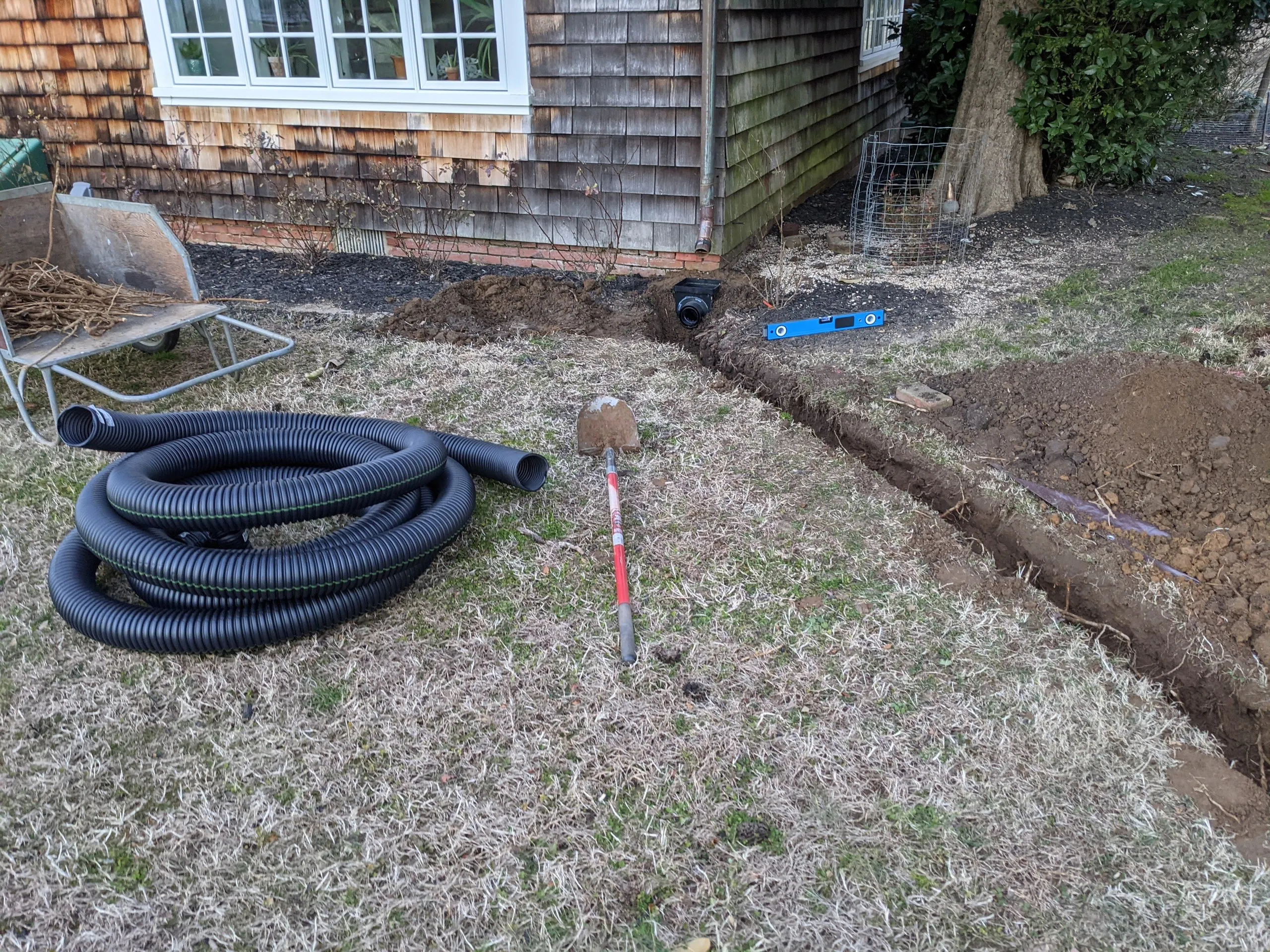
Coiled drain pipe and a shovel next to an open trench running from a catch basin along the foundation
Pipe and tools staged next to the trench
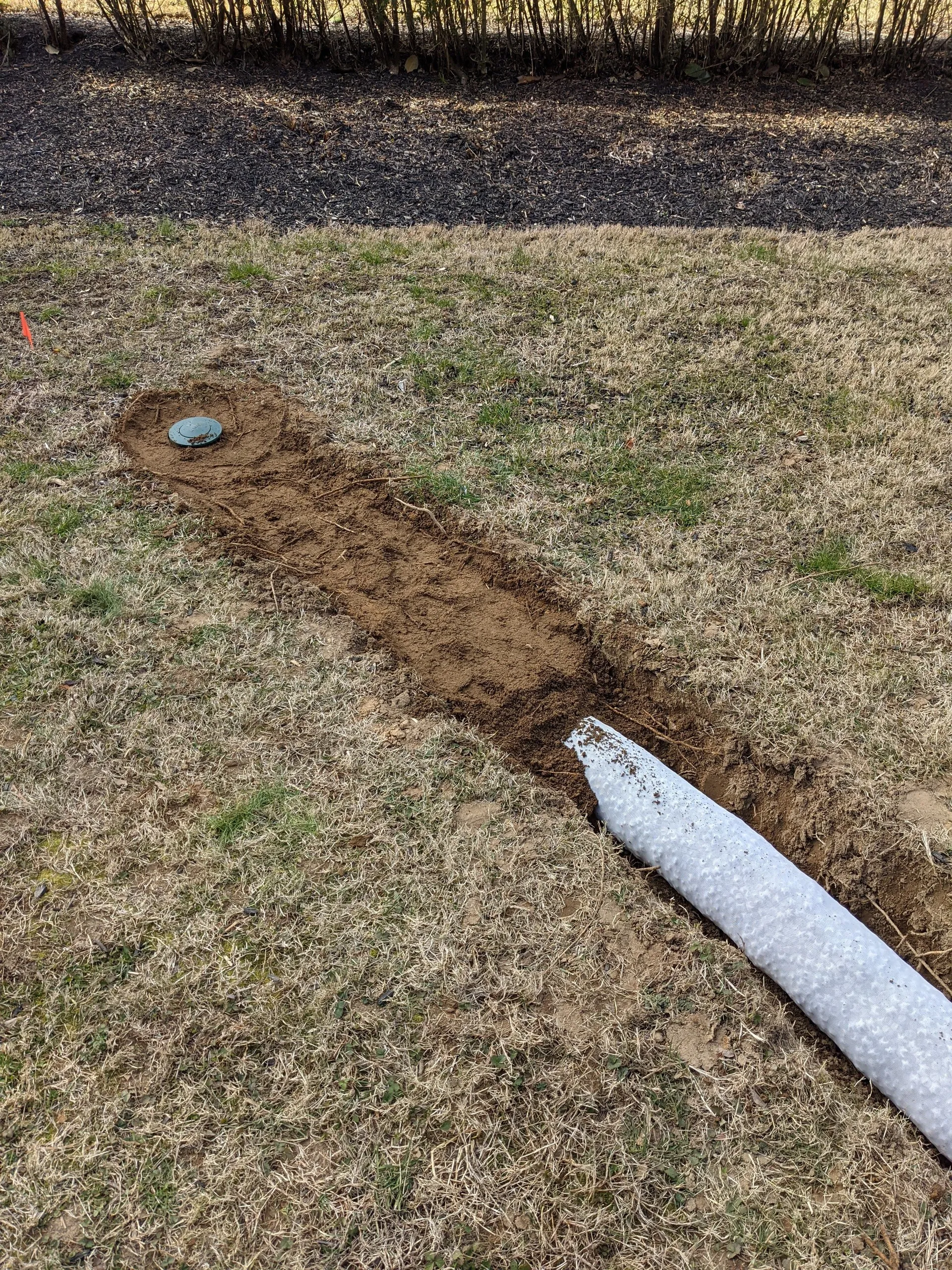
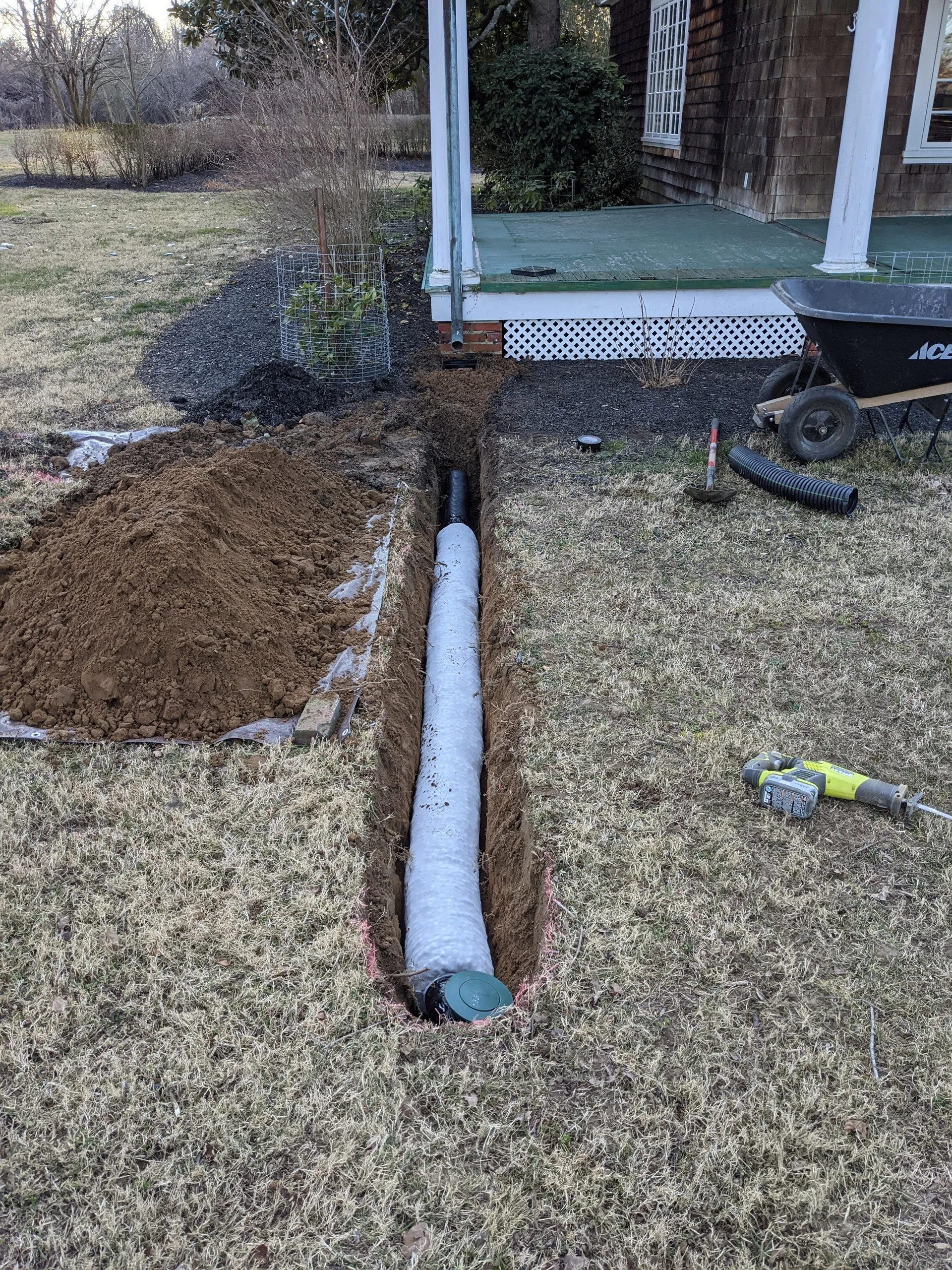
Open trench in the lawn leading to a round pop-up emitter cap, with the sock-wrapped pipe visible at the near end
Trench leading to a pop-up emitter
Catch basin connected to black corrugated pipe running down a trench next to the house
Basin connected to the pipe run
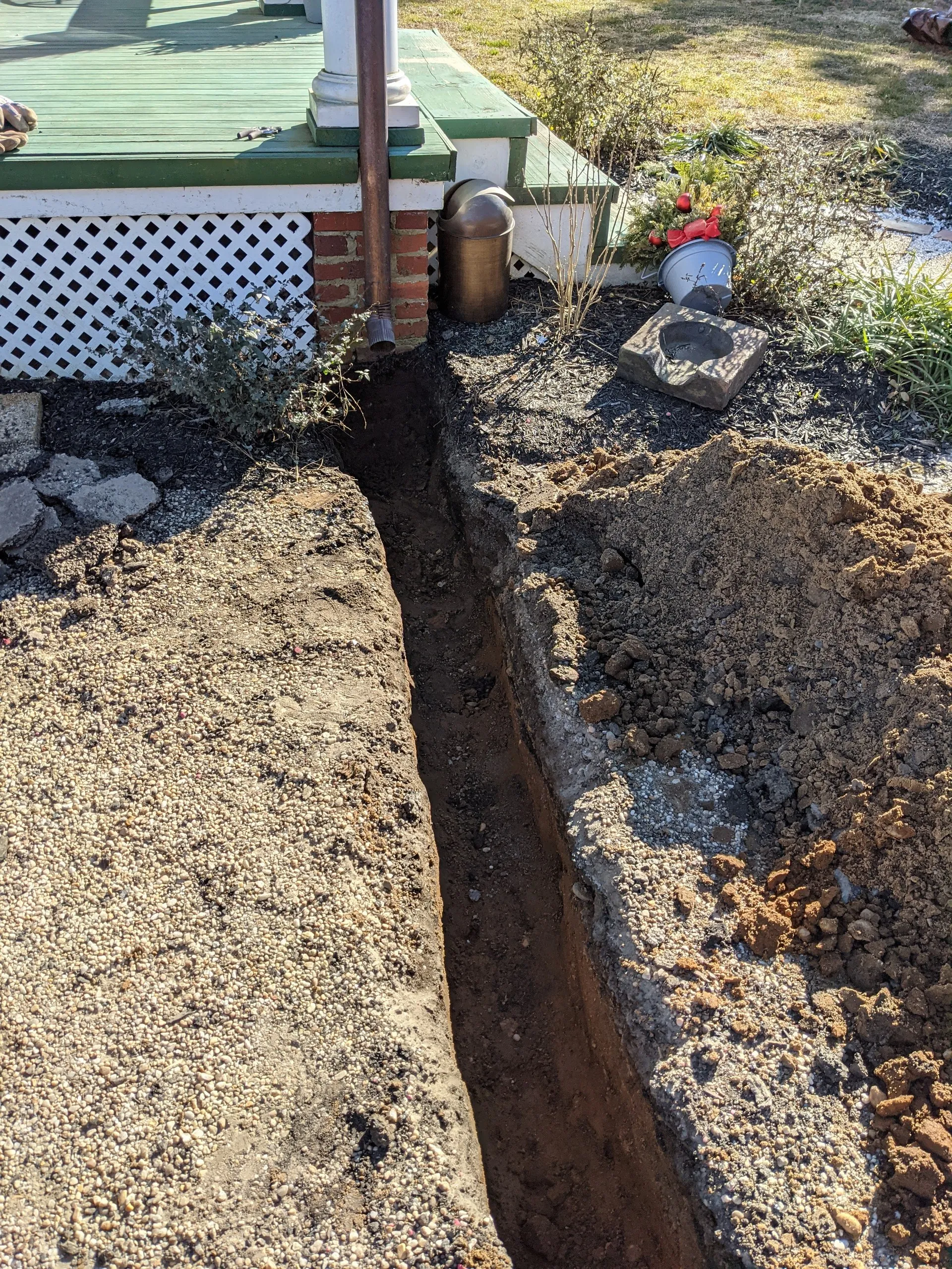
Deep trench dug alongside a porch foundation and a gravel path
Deep trench along the porch foundation
Long trench across the lawn with sock-wrapped pipe leading to a pop-up emitter, reciprocating saw left nearby
Full trench run to the emitter
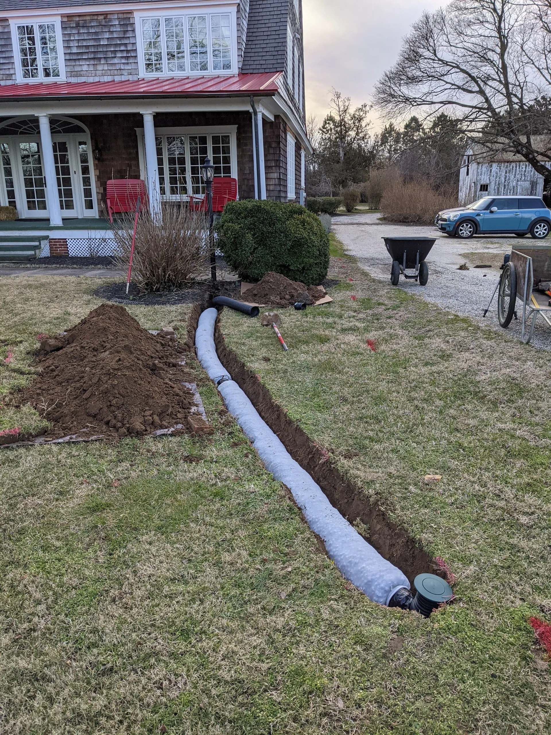
Long curving trench across the front lawn with sock-wrapped pipe leading toward a pop-up emitter, house and driveway in the background
Front yard trench run
Trench near a side porch with sock-wrapped pipe connected to a pop-up emitter, most of the run backfilled
Drain run nearing completion

Heavy rain was getting into the basement. The house has four separate roof sections draining to four downspouts, and none of them were doing anything to keep that water away from the foundation once it hit the ground - it just puddled at the base of the house and found its way in.

Before digging anything, I worked out how much water each downspout actually needs to handle. I estimated the roof area feeding each downspout, then sized the pipe and drainage capacity against Maryland’s design rainfall intensity of 4 in/hr and the first-flush volume for each roof section. The other side of the calculation is how fast the ground can actually accept that water - I used Hillel’s steady infiltration rates for general soil texture groups to get a percolation flow rate for the trench area at each basin, and checked that against the required flow rate to make sure the system wasn’t just going to back up.

The installed system: a catch basin at the base of each downspout, feeding a run of corrugated pipe (solid near the house, perforated and wrapped in a fabric sock further out) buried in a gravel-backed trench, terminating in a pop-up emitter that only opens once there’s enough head pressure behind it. The pipe run length, trench length, and offset from the house for each of the four downspouts came straight out of the spreadsheet - the northeast and northwest corners needed the longest runs, the southeast corner the shortest.