ProjectsPersonal
Self-driving zero turn lawnmower v2
A rewrite of the controller and the compass calibration, plus a simulator that runs the real Arduino code
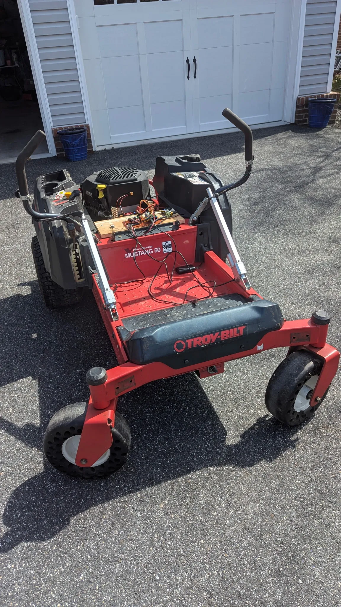
Version 1 cut one strip of grass and then stalled on the same three problems for a couple of years. The compass was being pulled around by the mower it was bolted to. The optical flow sensor only worked on cloudy days. And the GPS receiver was producing perfectly good coordinates that nothing was using.
Version 2 is a rewrite. Same mower, same actuators, almost none of the same code.
Splitting the problem in two
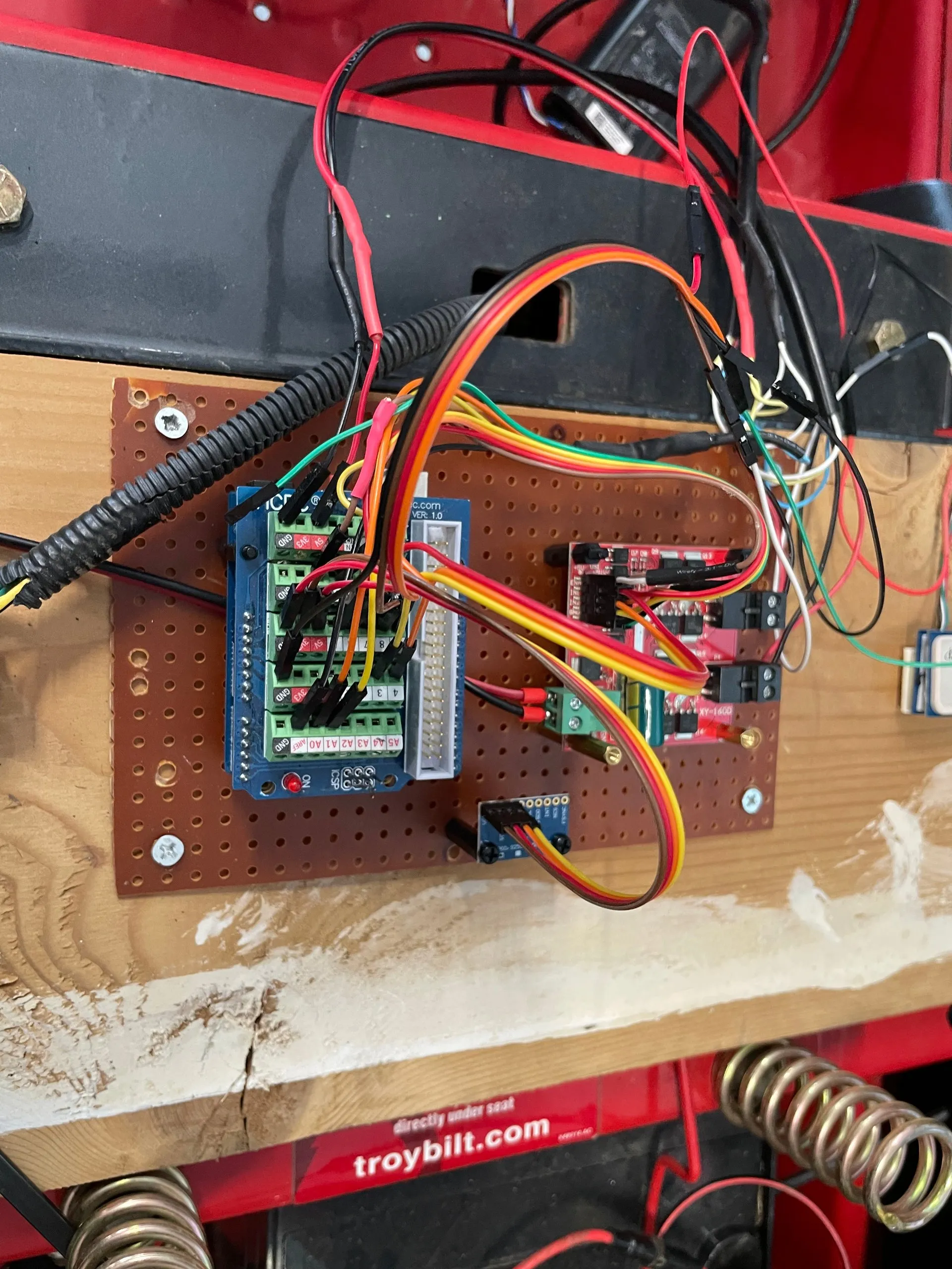
The biggest structural change: path planning moved off the Arduino and onto a laptop, and the two talk over a serial link.
Python (laptop)                     Arduino Uno
+-----------------------+           +--------------------------+
| Path planning         |  USB      | Yaw control              |
| Heading/speed command | <------>  | Actuator control         |
| Telemetry capture     |  serial   | IMU and GPS              |
+-----------------------+           +--------------------------+
The Arduino does only what has to happen in real time. Everything that benefits from floating point, plotting and a filesystem happens on the laptop.
The Arduino sends a telemetry packet ten times a second — heading, GPS position and quality, raw sensor readings, and where both actuators actually are — and gets back a heading and a speed. Packets are checksummed, and the mower stops if it has not heard a valid command in two seconds.
The compass problem, solved properly
Version 1’s headline failure was magnetic interference. A mower is a large steel frame with an engine, a battery and two motors on it, and a simple offset correction was never going to be enough.
The fix was to stop treating it as an offset. Spin a magnetometer through every orientation and the readings should trace a sphere. Sitting in all that iron, they trace a squashed, off-center egg instead. Fitting an ellipsoid to the readings recovers both how far off center it is and how much it is squashed, and correcting for both puts the sphere back.
I collected calibration data under the conditions that actually differ — engine off and running, actuators idle and moving, indoors and out — rather than one dataset and a hope. The calibration tool prints constants that get pasted straight into the firmware config.
Heading then comes from fusing the accelerometer, gyro and corrected compass, with a filter on top to smooth what is left. That code is shared between the calibration sketches and the main firmware so the two cannot drift apart.
The optical flow sensor did not get fixed. It got deleted. It was never going to work in direct sun, and once the heading was trustworthy it had nothing left to contribute.
Two control loops instead of one
Version 1 pointed a single PID loop at the heading error and asked it to produce actuator positions. That loop had to be gentle enough not to slam a 250 kg machine sideways, which made it too gentle to hold a line.
Version 2 splits the job:
- Outer loop, 20 Hz. Heading error in, a desired turn rate out. It is allowed to ask for at most 30°/s.
- Inner loop, 50 Hz. Compares that desired turn rate against what the gyro says is actually happening, and produces the difference between the two drive levers.
- Actuator loop, 100 Hz. Each linear actuator holds its commanded position against a median-filtered potentiometer reading.
Asking for a turn rate rather than a lever position is the change that mattered. The outer loop no longer has to know anything about how the machine responds — that is the inner loop’s job.
The mixing is deliberately lopsided: a correction pulls one lever back toward neutral rather than pushing the other one harder, so steering never speeds the mower up. Below 0.25 m/s it switches to rotating in place, with a little reverse bias because the machine creeps forward otherwise.
Measured top speeds came out at 2.61 m/s forward and 1.97 m/s in reverse.
Tuning it indoors
This is the part I would keep if I threw everything else away.
There is now a Python simulator — physics, simulated sensors with realistic noise, and a live view of the yard with the cut grass tracked on a 10 cm grid — so a path planning idea can be tried without starting an engine.
Simulating the mower is only half of it, though. The controller-in-the-loop rig goes further: it compiles the actual Arduino control code into a library that Python can call, fakes out the hardware it expects, and drives it against the simulated mower. It rebuilds itself whenever the firmware changes. So the gains I test in simulation are the gains the mower runs, executed by the same code.
Making that worth anything meant getting the simulated physics to match the real machine, which is what the recorded runs are for. Replaying real commands through the model and comparing the result against the recorded gyro turns tuning into a fitting problem — sweep the model’s parameters, keep whatever best reproduces a run that already happened.
The gains in the firmware config are labeled CIL-tuned. They were found
against step responses in that rig, not by turning a knob between passes.
Mowing a pattern
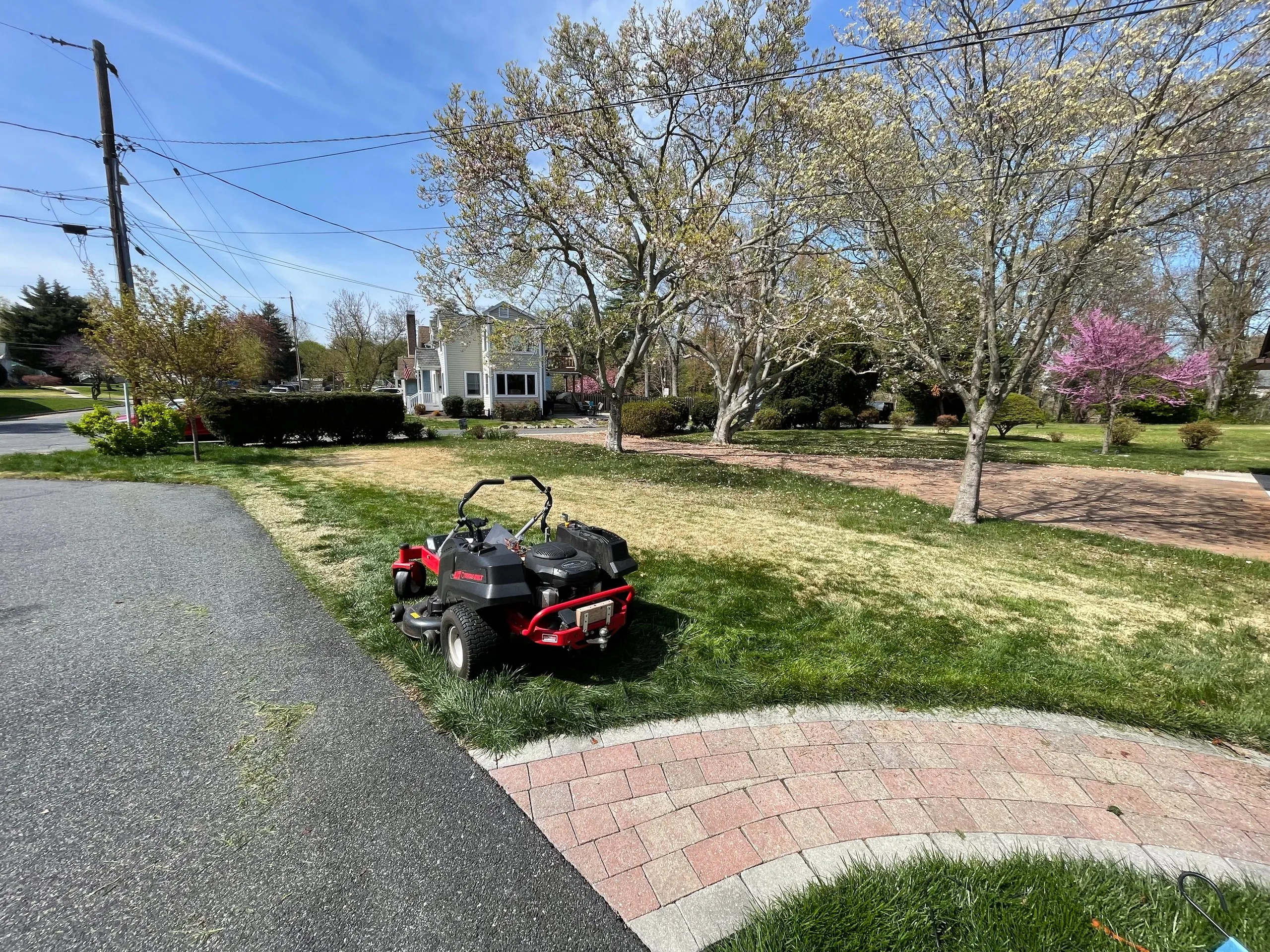
The yard is defined by three GPS corner points, each recorded by averaging 500 fixes. The planner works in local meters from there.
The pattern is what a person does: drive a pass, turn 180°, drive back with 0.75 m of overlap on a 1.5 m cut, repeat. Then a set of passes around the perimeter and a final trim sized to whatever strip is left over. Turn speed is worked out from the maximum turn rate so the machine comes out of the turn already lined up on the next pass instead of needing to be dragged onto it.
Position fixes are thrown away if the GPS quality is poor, and smoothed after that, because one bad fix mid-pass puts a kink in the grass that stays there until the next mow.
What is working now
- Heading holds. Across the final recorded runs, mean heading error per pass was −3.7° with a standard deviation of 3.4°
- The compass survives its own machine — which is the specific thing that killed version 1
- Actuator positioning is excellent, and was already good in version 1. Median filtering the feedback removed the spikes that made it chatter
- The controller-in-the-loop rig works, and is trustworthy once its physics parameters were fitted against real runs
- It drives real passes on the real yard: passes, turns and perimeter passes all run on hardware, under supervision
- Everything is instrumented. Runs log to CSV, and a replay tool re-runs a recorded pass so a change can be judged against the same conditions instead of a fresh run with different wind and different grass
What still needs work
- Position accuracy is the wall now, not heading. Across five configurations tested back to back, per-pass side-to-side error had a standard deviation between roughly 0.7 and 1.3 m. On a 1.5 m cut with 0.75 m of overlap, a meter of wander is the difference between a clean stripe and a missed one
- The tuning changes I tested were mostly a wash — better heading initialization, stronger lateral correction, calibrated cutting width, speed changes. None beat the baseline by more than the noise, which says the remaining error is coming from the GPS, not the tuning
- RTK is the obvious answer to that and I have not built it yet
- Still no obstacle avoidance on the real machine. The simulator detects collisions and aborts; the mower in the yard has no sensor that would let it do the same
- It has not been handed a whole yard end to end. Passes, yes. An unattended complete mow, no — and it should not be unattended until there is obstacle detection
- The Uno is full. Memory pressure already forced splitting the calibration routines into separate sketches and stripping unused code out of the sensor driver. Moving to a Mega is the easy way out
- The −3.7° heading bias is not noise. It is consistent across every run, so it is probably one wrong constant somewhere
Safety
Unchanged from version 1 in principle: no unsupervised operation, and a remote kill switch that works out to 1500 m and cuts the engine. Remote start and remote blade engagement are still there too. The one addition is in software — the mower stops itself if the laptop stops talking to it.